Microelectronics | StarView SV421 KVM Switch
Synopsis
I needed a simple KVM switch to bind two vintage computers to a single CRT monitor and AT keyboard. I did a fair amount of searching on the Internet for KVM switches but almost all were modern DVI/USB switching units. I needed an old model that switches VGA and PS/2 signals. I found the StarView SV421 switch by hazard while randomly looking around for interesting pieces of old hardware. I bought it for $15 and two weeks later I received it.
Disclaimer
This article is not to be treated as a do-it-yourself tutorial on how to fix, restore, rebuild, or improve this unit. This was not my initial intention. But you can consider this whole content as a general guideline, should you decide to attempt any service procedure on an identical or similar unit.
The entire documentation is just a reflection of my work and I cannot be held responsible if you damage your unit, or even harm yourself in the process.
Maintenance
The switch itself looks good with a few scratches and no dents. However, being a very old piece of equipment, I decided to open it up and replace the aging electrolytic capacitors. I searched my spare parts box and found out that I have enough capacitors of the right electrical specifications that I can overhaul this KVM switch. I didn't want to spend any money on this restoration, that's why I used all sort of capacitors that I had around: tantalum, solid polymer capacitors, electrolytics of different brands.
As this KVM switch will always be powered on, I wouldn't risk encountering catastrophic failures due to bad capacitors. Especially since this unit appears to have been built somewhere between 1996 and 1997, judging by the dates on the components.
Pictures
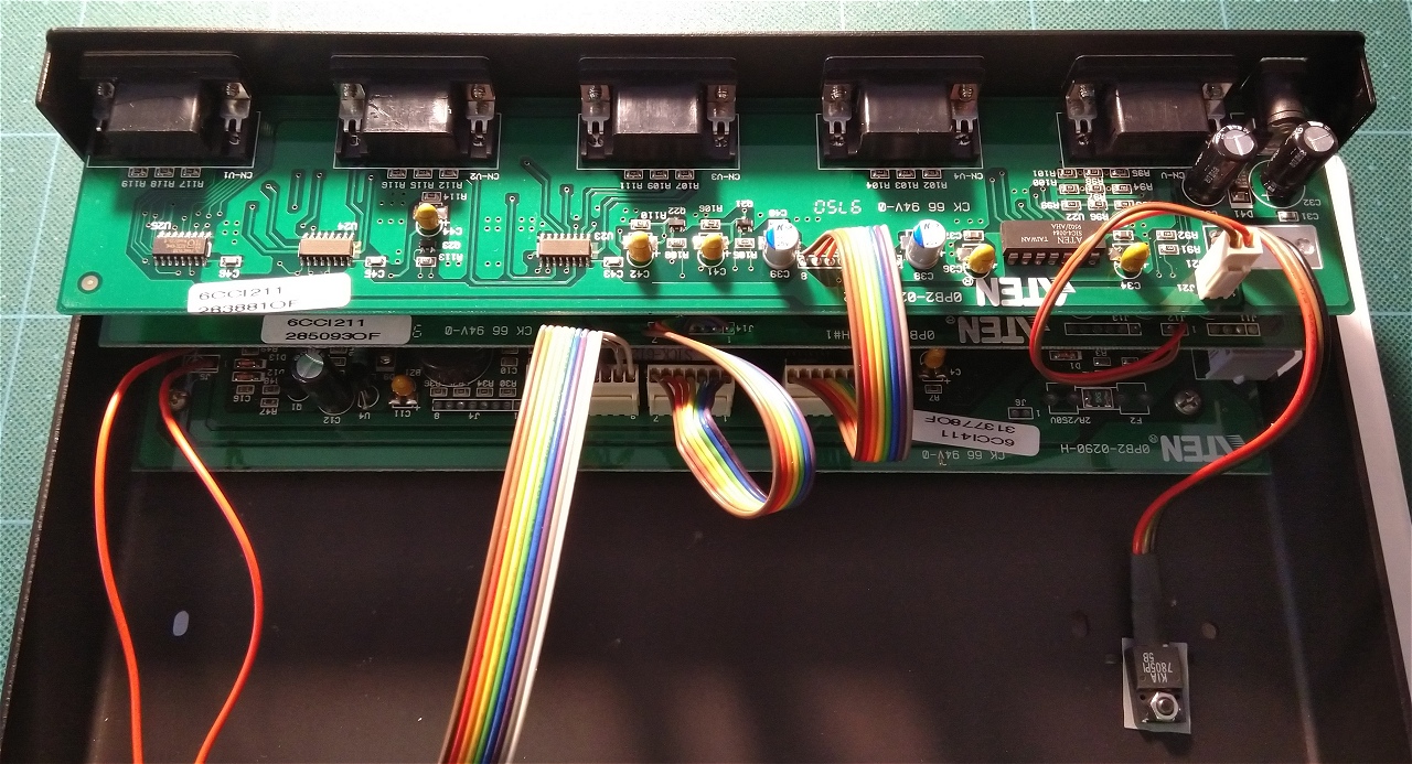
Here are some pictures that I took during this operation. There are three stacked PCBs, performing different tasks.
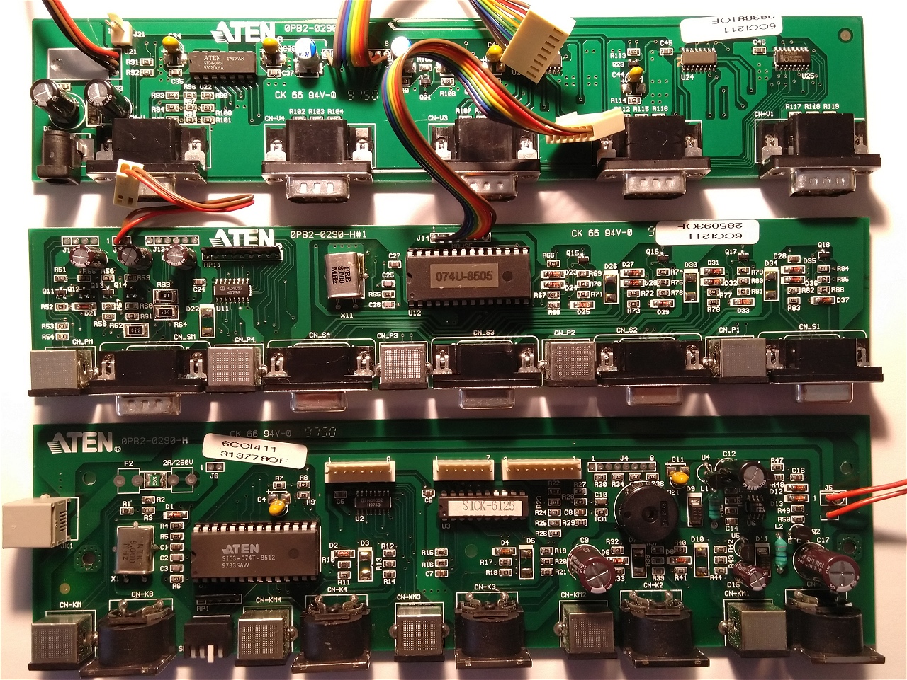
I mostly used Nichicon electrolytic capacitors. In some positions, I went with either solid polymer or tantalum capacitors.
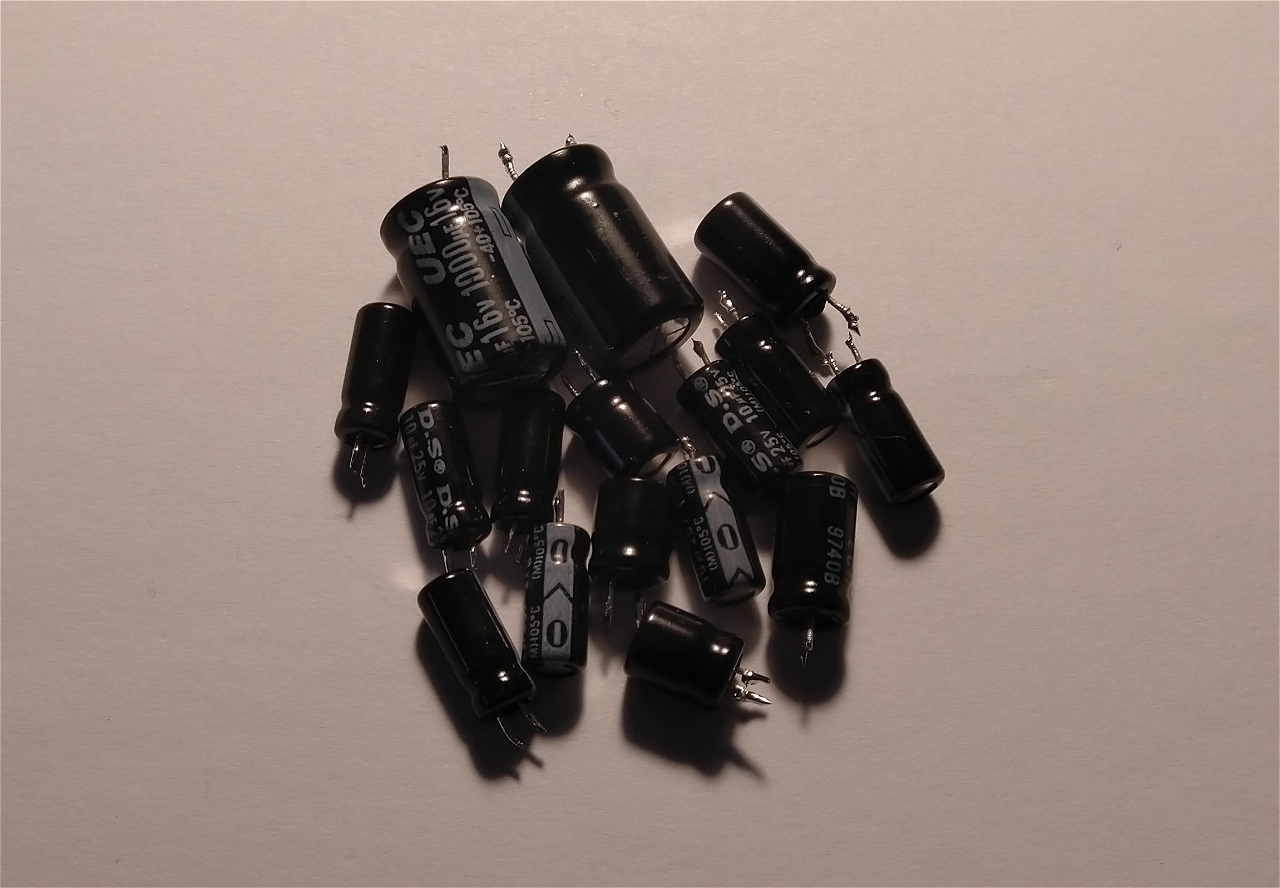
And these are the old capacitors. They were probably still good. But since it was just preventative maintenance, I didn't bother to test them.
This KVM switch should be good for many years of service.
Known Issues
However, when I installed the switch I found out that the keyboard port on CPU 1 did not work at all. I had a rough time testing different keyboard configurations both on the keyboard side and the PC side. But in the end, I concluded that the port itself is broken. Thankfully, I will use at most three PCs connected to the switch. And all ports from CPU 2 through CPU 4 are working.
(2024-edit) I now have three machines connected to the switch with plans to extend my retro setup to four. This means I will have to investigate why the keyboard port on CPU 1 isn't working.
Keyboard Shortcuts
In general, KVM switches can be operated via the attached keyboard through several key combinations. I tried some of the combinations that are known to work with modern KVM switches. But unfortunately, none worked.
There is almost no documentation available for the StarView SV421 KVM switch. I spent some time and did a deep web search for any data on this switch. The result was that I found some documentation for another similar model called SV421+ and, thankfully, some of the commands are working.
Selecting a Connected PC
You can select one of the four PCs connected to the switch by following the next steps.
- Enter command mode by pressing the following keys at once: ALT + CTRL + SHIFT.
- Select one of the PCs connected to the switch by pressing: 1, 2, 3, or 4.
- Validate the selection by pressing the ENTER key.
Scanning for Active Connected PCs
You can scan for the active PCs connected to the switch by following the next steps.
- Enter command mode by pressing the following keys at once: ALT + CTRL + SHIFT.
- Enter scan mode by pressing the 0 key.
- Validate the command by pressing the ENTER key.
- To exit scan mode press the SPACE key.
Quick Switching Between Connected PCs
You can use the keyboard to do quick switching between the PCs connected to the switch by following the next steps.
- Enter command mode by pressing the following keys at once: ALT + CTRL + SHIFT.
- Enter quick switch mode by pressing the 0 key.
- Validate the command by pressing the ENTER key.
- Switch to the previous connected PC by pressing the LSHIFT key.
- Switch to the next connected PC by pressing the RSHIFT key.
- To exit quick switching mode press the SPACE key.
Other Mentions
At some point in time, I will consider building a simple internal linear power supply for this KVM switch. At the moment, I use it with an external switching mode power supply that I had around in the junk parts box. But since the metal chassis has a lot of space inside to house a toroidal transformer and a small PCB with some rectifying diodes and a couple of filtering capacitors, I will go for this approach instead. I find a linear power supply more elegant (albeit less efficient) and there would be fewer ugly SMPS units in the mains socket. I like unity and when I look at the mains extender, it looks like crap with a lot of assorted black adapters side by side.
But that is a project for one of those rainy days.
Internal Power Supply
Here we are in July 2023; no rainy days but temperatures of around 40 °C at noon. A good time for indoor electronics projects.
I initially wanted to build a dedicated linear power supply, as described above. A couple of months ago, I rebuilt a 12 V / 2 A Switching Mode Power Supply and I modified it for an output of 7.5 V. Thus, I decided to install it in the StarView switch. I used a thin layer of double-sided thermal tape to secure the power supply assembly to the steel chassis.
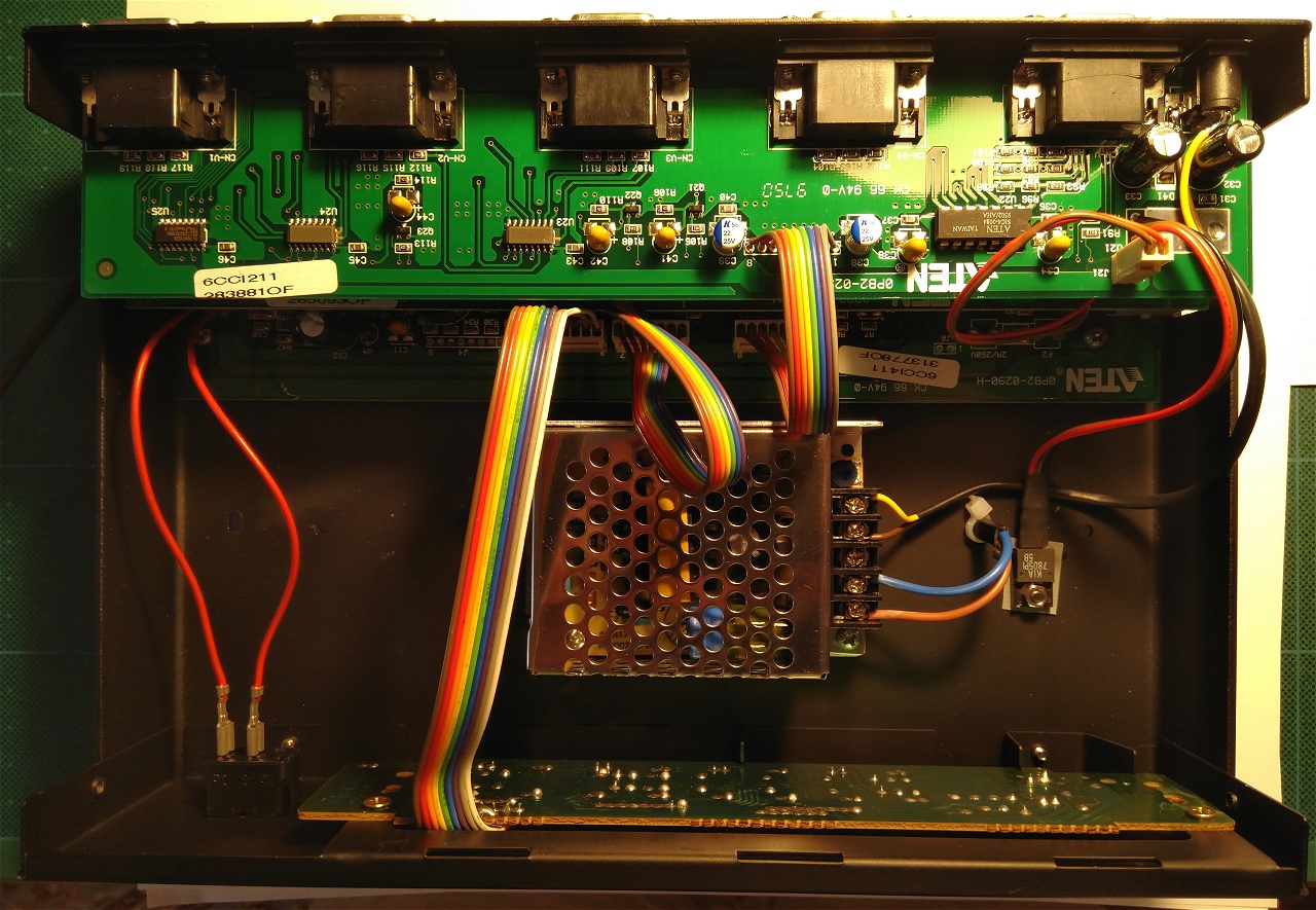
Conveniently enough, there was an oval hole next to the linear regulator IC. I used it as an entry point for the mains wire as it fits perfectly. I used a simple plastic clamp to secure the cable.
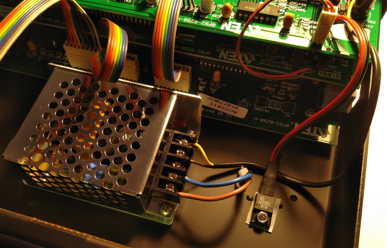
Finally, I soldered the supply wires directly to the former DC power connector. Not that pretty but effective.
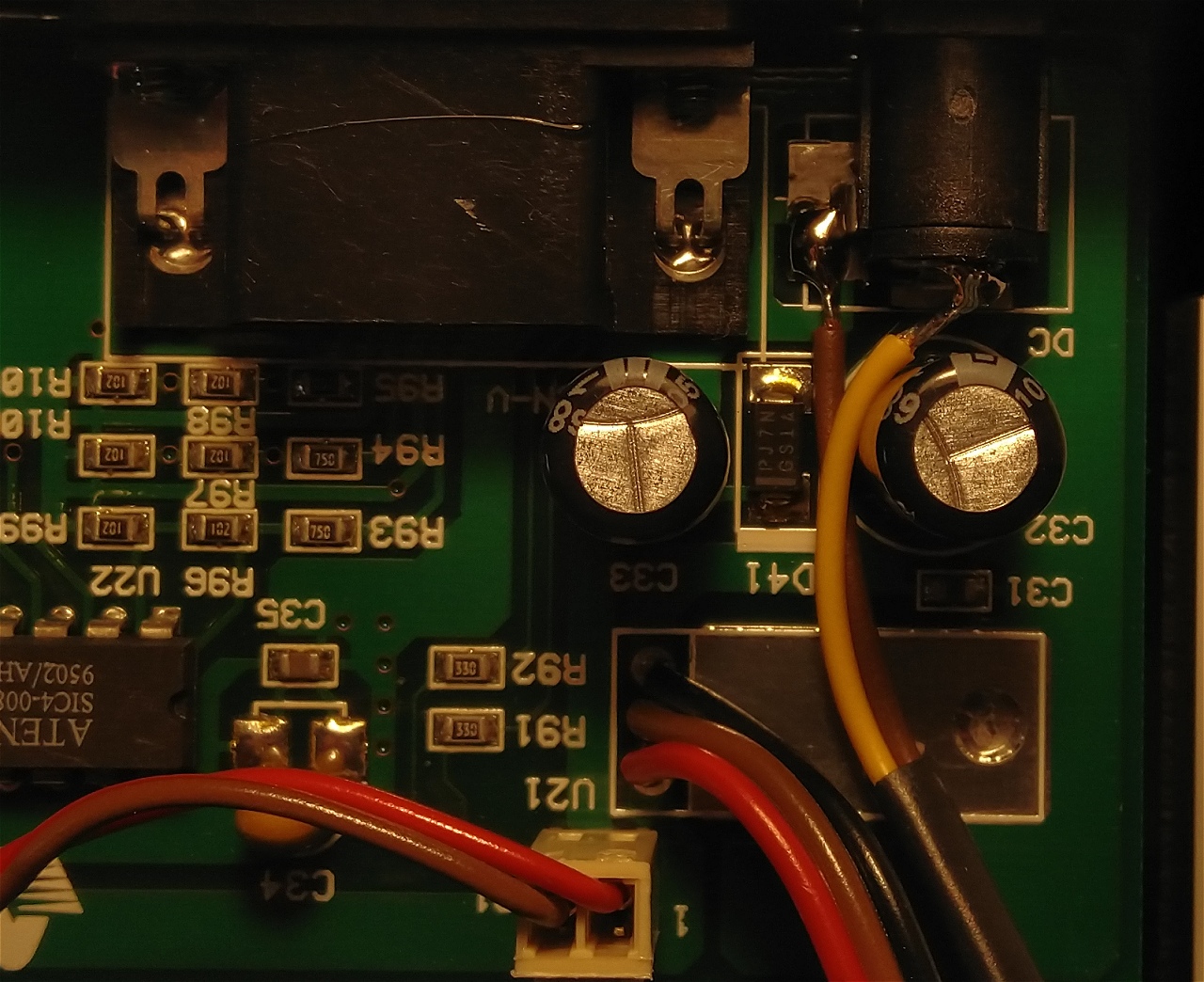
I'd say the modification went straightforward and the results are pretty awesome.
Your Help Matters
This content is provided as-is and is not for commercial purposes. It reflects my experiments and research and should be treated as such. I release my work to the public for educational purposes. I did all this at my own expense and in my free time. So if you like my work, or find it useful or inspiring for your projects, please consider making a donation.
Copyright © 2004- Alexandru Groza
All rights reserved.
VER. 1.0 | REV. A